The purpose of the sprinkler system; to provide early response to the fire and to discharge the amount of water on the design area within a certain period of time to control and extinguish the fire. The diameter of the fixed pipe installation that supplies water to the sprinkler system should be determined according to the hydraulic calculations to be made.
Sample Sprink Calculation
1- First of all, in accordance with the regulation on the fire protection of the buildings, criteria for the building’s hazard class and sprinkle design are determined. The building we sample is the hotel;
– Hazard Class: Medium Hazard – 1 (Selected from Annex-1 / B Medium Hazard Hazard Areas table)
– Application Area: 72 m² (Design Density in Annex-8 / B Sprinkler System is selected from the table)
– Design Density: 5 lt / dk.m² (selected from the Design Density table in Annex-8 / B Sprinkler System)
– Sprinkler Protection Area: 12 m² (maximum protection area for medium danger for 1 sprinkle)
– Km: 80 (K factor is 80 for sprinkler with nominal 1/2 “nominal ratio.
– Pipe Type: Black Steel (Wet and Tough System)
– C Value: 120
2- After designing in the project, use diameters according to the number of sprinkles using the following NFPA table for diameter.
| Fire Installation Pipe Diameters, NFPA 13-1999, Pipe Tray Method | |||||||
| Pipe Diameter (Steel) | Number of Light Danger Sprinklers | Number of Medium Danger Sprinklers | |||||
| one” | 2 Sprinkler | 2 Sprinkler | |||||
| 11/4 “ | 3 Sprinkler | 3 Sprinkler | |||||
| 11/2 “ | 5 Sprinkler | 5 Sprinkler | |||||
| 2nd” | 10 Sprinkler | 10 Sprinkler | |||||
| 21/2 “ | 30 Sprinkler | 20 Sprinkler | |||||
| 3 “ | 60 Sprinkler | 40 Sprinkler | |||||
| 31/2 “ | 100 Sprinkler | 65 Sprinkler | |||||
| 4 “ | There is a protection area limitation. | 100 Sprinkler | |||||
| 5 “ | It is unnecessary. (Over-engineering) | 160 Sprinkler | |||||
| 6 “ | It is unnecessary. (Over-engineering) | 275 Sprinkler | |||||
| 8 “ | It is unnecessary. (Over-engineering) | There is a protection area limitation. | |||||
3- Number of sprinkles opened in the critical area is 72 m² / 12 m² = 6 pieces. In each of the points in the critical line in the 2-line table direction and in the lines outside the critical area, only the number of points with the diameter change is given.
4- We will use it in calculations Identify Equivalent Length Values, Pipe Diameters, Coefficient of C, and Correction table and formulas to use.
- Equivalent lengths of fittings
| Nominal diameter (Inch) (mm) | 90 Elbow (M) | Sign (M) | Butterfly Valve (m) | Sliding Valve (m) | Check Valve (Çalparal a) | Alarm Van (m) | |
| one | 25 | 0.6 | 1.5 | – | – | 1.5 | – |
| 11/4 | 32 | 0.9 | 1.8 | – | – | 2.1 | – |
| 11/2 | 40 | 1.2 | 2.4 | – | – | 2.8 | – |
| 2nd | 50 | 1.5 | 3.1 | 1.8 | 0.3 | 3.4 | – |
| 21/2 | 65 | 1.8 | 3.7 | 2.1 | 0.3 | 4.3 | – |
| 3 | 80 | 2.1 | 4.6 | 3.1 | 0.3 | 4.9 | – |
| 4 | one hundred | 3.1 | 6.1 | 3.7 | 0.6 | 7.6 | 8.5 |
- Physical properties of steel pipe
| Nominal diameter | Outside Diameter | Meat Thickness | Inner diameter | |
| inch | mm | mm | mm | mm |
| one | 25 | 33.7 | 3:25 | 27.2 |
| 11/4 | 32 | 42.4 | 3:25 | 35.9 |
| 11/2 | 40 | 48.3 | 3:25 | 41.8 |
| 2nd | 50 | 60.3 | 3.65 | 53.0 |
| 21/2 | 65 | 76.1 | 3.65 | 68.8 |
| 3 | 80 | 88.9 | 4:05 | 80.8 |
| 4 | one hundred | 114.3 | 4:50 | 105.3 |
- Tube friction loss coefficients
| Pipe Type | Friction Loss Coefficient C |
| Black Steel Pipe (Dry and pre-reacting system) | one hundred |
| Black Steel Pipe (Wet and Ramp System) | 120 |
| Galvanized Pipe | 120 |
| PE Pipe | 150 |
- Correction coefficients
| Friction Loss Coefficient C | Correction Factor |
| one hundred | 0713 |
| 120 | 1:00 |
| 150 | 1:51 |
- Formulas
a) Sprink Minimum Water Flow = Q = (d) x As
d = Design Density (lt / dk m²), As = Application area of one sprinkler (m²)
b) Minimum Pressure Qm = Km × √P
Qm: Flow (lt / min), Pm: Pressure (bar), Km: K Factor – Metric (Units) K = 5.6 Km = 80
The Km value will vary depending on the value of your sprinkle orifice.
c) Static Pressure
P st = hx 0.098
h = desired height to calculate the pressure with ground elevation (m)
P st = Pressure (Bar)
d) Hazen Williams Formula, Loss of Friction
Pm = 6.05 x [Qm ^ 1,85 / (C ^ 1,85 × dm ^ 4,87)] × 10 ^ 5
Pm = Friction resistance in unit length pipe (bar / m)
Qm = Flow (lt / min)
C = Friction Loss Coefficient
dm = pipe inner diameter (mm)
e) Balancing Formula
Qbalans = Qd × (√Pb / √Pk)
Qbalans = Balance Debacle
Q = Low Flow Rate
Pb = Large Pressure Loss (bar)
Pk = Small Pressure Loss (bar)
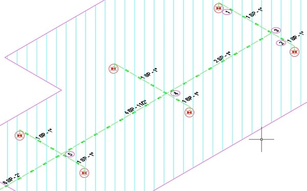
5- Let’s start with the calculation steps of the pump flow rate and pressure loss that will occur in case of 6 sprinkling of the system. The following illustration shows the critical area. You can download the file as dwg. Sample Sprink Column Schematic: Sample Sprink Calculation Autocad Download
Let’s start the calculations according to the numbering process.
– Sprinkle start Q = (d) x As = 5 x 12 = 60 l / min
– Flow Pressure Qm = Km × √ P – 60 = 80 × √ P – P = 0,5625 bar
– 1 line
a) Pressure loss due to friction
Pm = 6.05 x [Qm ^ 1,85 / (C ^ 1,85 × dm ^ 4,87)] × 10 ^ 5
Pm = 6.05 × [60^ 1,85 / (120^ 1,85 × 27,2 ^ 4,87)] × 10 ^ 5 = 0,0173 bar
b) Equivalent Length for 1 line resistance values
Straight Pipe: 2.1 m
1 piece Elbow: 1 “for table diameter 0.77
Total = 2.1 + 0.77 = 2.87
c) Psytrity = 0.0173 x 2.87 = 0.0497 bar
d) P totample = 0,5625 + 0,0497 = 0,6122 bar
e) Branch Debt = Qm = Km × √ P = 80 × √0,6122 = 62,59 l / min
– 2 lines
a) Pressure loss due to friction
Pm = 6.05 x [Qm ^ 1,85 / (C ^ 1,85 × dm ^ 4,87)] × 10 ^ 5
Pm = 6.05 ↨2 [60^ 1,85 / (120^ 1,85 × 27,2 ^ 4,87)] × 10 ^ 5 = 0,0173 bar
b) Equivalent Length for 1 line resistance values
Flat Pipe: 1,0 m
1 piece Elbow: 1 “for table diameter 0.77
Total = 2.1 + 0.77 = 1.77
c) Psytrity = 0.0173 x 1.77 = 0.0307 bar
d) P totample = 0.5625 + 0.0307 = 0.5932 bar
e) Branch Debt = Qm = Km × √P = 80 × √0,5932 = 61,61 l / min
– 3 lines
1 and 2 are connected to the line t. In this section we need to find out by means of the total debial balancing method which will provide 2 lines of pressure.
a) Qbalans = Qd (√ Pb /√ Pk) = 61,61 (√ 0,6122 /√ 0,5932) = 62,59 l / min
b) Qbransman = Qbalans + Qbarship = 62.59 + 62.59 = 125.2 lt / min
c) 3-way line Friction-induced pressure loss
Pm = 6.05 x [Qm ^ 1,85 / (C ^ 1,85 × dm ^ 4,87)] × 10 ^ 5
Pm = 6.05 ↨× [125,2^ 1,85 / (120^ 1,85 × 27,2 ^ 4,87)] × 10^5 = 0,0675 bar
d) Equivalent Length for Resistance Values of 3-Wire Line
Flat Pipe: 3,8 m
1 te: table for 1 “diameter 1,5
Total = 3,8 + 1,5 = 5,3
e) Psychosis = 0,0675 × 5,3 = 0,3578 bar
f) Ptoplam = Pöncekit + P3 line = 0,6122 + 0,3578 = 0,97 bar
(Pöncekit, total pressure of the previous line 0.5625 + 0.0497 = 0.6122 bar)
– 4 lines
In this section, 3 lines connected to this point are connected to the same line 1 and 2 line. If it were not for the same, we would have to recalculate these merging lines. In this section, we need to find the new press release method according to the biggest press to provide the appropriate press in these lines.
As far as the greatest pressures 1, 2 and 3 are concerned, 3 are the lines. (Because 1 and 2 are the same, you can not give this number different numbers if you do not want to print, but you do not have to number them extra if the pressures are the same.)
Let’s balance the line with 3 to 1, then 3 to 2.
a) 3 to 1 Qbalans = Qd x (√ Pb /√ Pk) = 62,59 × (√0,97 / √0,6122) = 78,79 l / min
b) 3 to 2 Qbalans = Qd x (√ Pb /√ Pk) = 61,61 × (√0,97 / √0,5932) = 78,79 l / min
c) Qbranman = Qbalans + Qbalans + Qbang = 78,79 + 78,79 + 125,2 = 282,8 lt / min
d) Line 4 Pressure loss due to friction
Pm = 6.05 x [Qm ^ 1,85 / (C ^ 1,85 × dm ^ 4,87)] × 10 ^ 5
Pm = 6.05 x [282,8^ 1,85 / (120 ^ 1,85 x 41,8 ^ 4,87)] x 10 ^ 5 = 0,0376 bar
e) Equivalent Length for resistance values of 4 lines
Flat Pipe: 3,8 m
1 pcs teat: table for the diameter of 11/2 “2,4
Total = 3.8 + 2.4 = 6.2
f) Psychosis = 0.0376 × 6.2 = 0.2332 bar
g) Ptoplam = P3 + P4 line = 0,97 + 0,2332 = 1,2032 bar
– 5 lines
In this section, 4 lines connecting to this point line 1 and 2 line are combined with the same line. If it were not for the same, we would have to recalculate these merging lines. In this section, we need to find the new press release by balancing according to the greatest press to provide the pressure for these lines.
The maximum pressure is 1, 2 and 4 and 4 is the line. (Because 1 and 2 are the same, you can not give this number different numbers if you do not want to print, but you do not have to number them extra if the pressures are the same.)
Let’s balance the line with 4 to 1, then 4 to 2.
a) 4 to 1 Qbalans = Qd x (√ Pb /√ Pk) = 62,59 × (√1,2032 /√ 0,6122) = 87,75 l / min
b) 4 to 2 Qbalans = Qd × (√Pb / √Pk) = 61,61 × (√1,2032 / √0,5932) = 87,75 l / min
c) Qbransman = Qbalans + Qbalans + Qbars = 87,75 + 87,75 + 282,8 = 458,3 lt / min
d) Line 5 Pressure loss due to friction
Pm = 6.05 x [Qm ^ 1,85 / (C ^ 1,85 × dm ^ 4,87)] × 10 ^ 5
Pm = 6.05 × [458,3^ 1,85 / (120^ 1,85 × 53,4,4,87)]× 10^ 5 = 0.0289 bar
e) Equivalent Length for 5 line resistance values
Straight Pipe: 11,8 m
1 tee, 3 elbows, 1 butterfly valve for table 2 “diameter 9,60
Total = 11,8 + 9,6 = 21,40
f) Psychromatic = 0.0289 × 21.4 = 0.6188 bar
g) Ptoplam = P4 + P5 line = 1,2032 + 0.6188 = 1,8220 bar
If you pay attention after you have done the balancing process, you will notice that there is no new flow and balance calculation from now on the critical hattan in this project. If there is only a change in diameter, we will calculate the pressure losses in these areas. In addition, if there are lines such as “te” during the diameter change, we will take these parts as elbows because the calculations are done by predicting that the water is going straight to the critical area. Otherwise, there is no point in getting a critical area.
– 6 line (for 2 “to 21/2” switch)
a) Line 6 Pressure loss due to friction
Pm = 6.05 x [Qm ^ 1,85 / (C ^ 1,85 × dm ^ 4,87)] × 10 ^ 5
Pm = 6.05 × [458, 3^1,85 / (120^ 1,85× 68,8^4,87)] × 10^ 5 = 0.0081 bar
b) Equivalent Length for Resistance Values of 6 Wire
Straight Pipe: 3.0 m
1 elbow 21/2 “diameter for table 1.90 (We took it as an elbow)
Total = 3 + 1.9 = 4.90
c) Psychosis = 0,0081 × 4,9 = 0,0398 bar
d) Static Height 3 m Ps = 0.098 * 3 = 0.294
e) Ptoplam = P5 + P6 line + Ps = 1,8220 + 0.0398 +0,294 = 2,1558 bar
– Line 7 (for 21/2 to 3 “)
a) Line 7 Pressure loss due to friction
Pm = 6.05 x [Qm ^ 1,85 / (C ^ 1,85 × dm ^ 4,87)] × 10 ^ 5
Pm = 6.05 × [458, 3 ^ 1,85 / (120 ^ 1,85 x 80,8 ^ 4,87)] 10 ^ 5 = 0.0037 bar
b) Equivalent Length for 7 line resistance values
Straight Pipe: 27 m
9 pieces of elbows for table 3 “diameter 21,60 (We bought the tails as elbows)
2 butterfly valves, 1 check valve 3 “diameter for table 11,1
Total = 27 + 21.6 + 11.1 = 59.70
c) Psychosis = 0.0037 * 59.70 = 0.2214 bar
d) Static Height 27 m Ps = 0.098 * 27 = 1.7640
e) Ptoplam = P6 + P7 line = 2,1558 + 0,2214 + 1,7640 = 4,1412 bar
In this direction, 458,3 l / min and 4,14 bar flow and pressure loss occur. When we converted, 27,5 m³ / h and 41,4 mSS flow and pressure loss occur.
If you look carefully at first the NFPA table line in the inner line of the line was done and the main line was the hydraulic calculations by taking my experience as the final 3 “. If the pressure loss value is high, increasing the diameter will lower the diameter. For this reason, it is not right to choose the main line diameter especially by looking at the table, it is necessary to determine the correct diameter by hydraulic calculation. In this case, the correct and unnecessarily large diameter will not be selected.
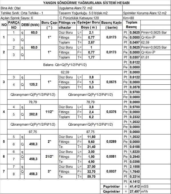
The calculation file looks like this.
In addition, there is a fire cabinet, a hydrant and a sprink system in your fire system. As a result of hydraulic calculations for medium danger 1, your sprinkle output is 458 l / min and 42 mSS, as in the above example.
Because of the spring in the system, a total of 458 + 100 + 400 = 958 l / min is obtained by adding 100 l / min for the fire cabin and 400 l / min for the hydrant from the “Additional Water Requirements for Fire Cabinets and Hydrant System” min – For a flow rate of 57,5 m³ / h, your pump flow should be approx. 58 m³ / h.
For pressure loss, we found sample sprink pressure loss of 41 mss, in other cases, for example firefighter 65 mss, hydrant 80 mss. In general, the process is to select the pump at 58 m³ / h 80 mss, taking the highest pressure loss to stay on the safe side.
However, the correct pump selection must be made by looking at the pump curve. As the flow rate increases, the pressure loss decreases. As the flow rate decreases, the pressure loss increases.Choosing the direction of the pump curve will help you save energy by preventing you from choosing a pump at high capacity.
Dear Guests, if the above information is a matter of sight, you can help to reach the most correct solution by commenting.
Mechanical Installation Information and News Portal
Fire Installation Editor


hello. what does ms stand for? thanks
mSS: It is the pressure exerted on the surface by the vertical action of the 1 meter high water column.