AHU selection principles are explained in detail with examples of calculations. Air briefly touch on the basics before plant selection.
basic environment in HVAC applications, a mixture of dry air and water vapor, “Moist air” in other words, is atmospheric air. Moist air thermodynamics or “Psychrometry”, is a science that studies the properties of air and water vapor mixture.
HVAC Engineer, entering the device, leaving the air passing through and changes in thermodynamic properties should certainly know. Psychrometric diagram is utilized to do this. Therefore, for the HVAC Engineer psychometric it is an indispensable tool diagram.
In 1911, Willis h.carri thermodynamic relations between the moist air features a “Psychometric Diagram” by the time of its publication with the HVAC industry has made a very important contribution to this formula and formed the basis of the HVAC industry.
Moist AHU Process
1. Heating or Cooling:
When heated or cooled without losing the amount of moisture in the humid air psychrometric diagram moves in a horizontal straight line on. Central heating in the coils is a good example.

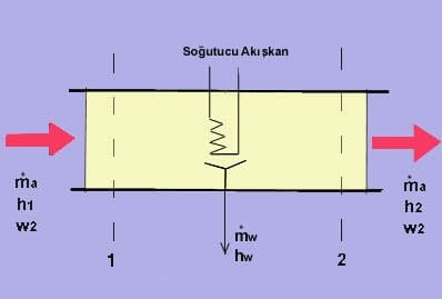
2. Cooling & Drying:
When moist air is cooled to a temperature below its dew point, wherein a portion of the water vapor will be condensed and separated from the air. The following figure is a schematic illustration of cooling and drying device.
3- Adiabatic humidification:
Moist air into the environment in an adiabatic (no heat transfer) steam or water is injected when the humidity rises. If injected vapor is known in the warmth and if possible to find the value of the enthalpy of the steam table. Humidification process will be held up to the room to ensure the comfort humidity conditions to determine the rate of humidity in the humidifier output will be easy.

If moist air wet bulb temperature of the injected water, until the saturation point on a constant wet bulb temperature curve (100% RH) continues the process. Humidified air dry bulb temperature will increase the humidity falls. In practice, this process “Evaporative Cooling” is known as the 100% RH point before the wet weather ends the process. efficiency value of the humidifier or evaporative cooler, will be instrumental in determining the point of origin.
4- Two separate Airflow the adiabatic mixture:
For use in an air handling unit is a common process. Figure 1.5 shows a mixture of two air currents.

Standard Air Concept
Basic formulas related to HVAC account “Standard Air” is based on values. ASHRAE standard air defined as follows.
According to the “standard conditions”, sea level;
• has at 15 ° C.
• It is considered as an ideal gas.
• The barometric pressure of 101 325 kPa is.
According to ASHRAE ‘eat, standard air density of 1,204 kg / m3 was adopted. This value of 15 ° C until saturated with water vapor at 20 ° C is equivalent to the dry air density value. The reason why the standard temperature of 15 ° C is to be accepted, usually from the HVAC coil process, the air passing through the fan and the channel is at a value close to that temperature. Standard accounts are usually made using the air value does not include margin of error of 2% or 3% more than in the HVAC account and use readily accepted.
The ideal gas equation of -50 to + 50 ° C temperature of the moist air problem of use of standard atmospheric pressure raises an error rate of less than 0.7%. Also, this margin of error lower than atmospheric pressures (above sea level) is reduced even further. Therefore giving enough precision to use in the HVAC field, and the simple ideal gas equation is easy to use.
However, atmospheric pressure should always be considered as sea level (101.325 kPa) and should be corrected for different altitudes. This means that we use psychometric reveals the need to be adjusted according to the height of the diagram.
Standard atmospheric weather data in the following Table 1 are given for altitude up to 10000 m.
| Standard Atmospheric Data | ||
| height M | Temperature ° C | Pressure kPa |
| -500 | 18.2 | 107.478 |
| 0 | 15.0 | 101.325 |
| 500 | 11.8 | 95.461 |
| one thousand | 8.5 | 89.874 |
| 2000 | 2.0 | 79.495 |
| 3000 | -4.5 | 70.108 |
| 4000 | -11.0 | 61.640 |
| 5000 | -17.5 | 54.020 |
| 6000 | -24.0 | 47.181 |
| 7000 | -30.5 | 41.061 |
| 8000 | -37.0 | 35,600 |
| 9000 | -43.5 | 30.742 |
| 10000 | -50.0 | 26.436 |
1989 ASHRAE Handbook-Fundamentals Chp.6.8 Table-3
Table 1: Height Optional Standard Atmospheric Data
Height reduce the density of the air, because it reduces the thermal capacity in the air conditioning plant causes a drop in pressure loss in the system. Changes in pressure loss is of great importance in the selection of the fan in the air handling units. Fan selections are based on the volume flow.selection of the fan manufacturer prepared for sea-level curve even if the fan flow to where they used the same volume. However, account must be adjusted according to the height of the fan pressure.
Pressure losses in the system before selecting any fan should be calculated. As it is known,
• losses within the device
• Device off losses (formed in the channel)
• System effect (System Effect) are the losses incurred.
Built-in heat losses, the cooling coil, humidifier from, the dampers, filters, etc. come from the interior air handling equipment. Domestic manufacturers of air handling device according to the configuration of the design of our catalogs pressure losses must be collected separately determined for each element. The resulting value is the sum of sea level pressure losses within the device.
After this brief introduction, let’s examine issues associated with the publications that contain detailed information. [1]
[pdfviewer width=”600px” height=”800px” beta=”true/false”]https://googledrive.com/host/0B577_s9dv9PcYUVyZktpQ012Vms[/pdfviewer
Examples of broadcast air conditioning accounts related to Plant Selection examine.
[pdfviewer width=”600px” height=”800px” beta=”true/false”]https://googledrive.com/host/0B577_s9dv9PcbEJxU2YzcVZnVXc”]
In light of this conditioning you can download various Excel calculations and programs related to plant Account.
| AHU Calculation Programs | ||||
| Explanation | Download Link | |||
| AHU Calculation Excel [2] |  air conditioning-plant-calculation.xls air conditioning-plant-calculation.xls | |||
| Systemair Air Handling Unit Selection Program | Systemair Air Handling Program Download | |||
| Teknofor the AHU Selection Program | Teknofor the Air Handling Request Form | |||
| ACS AHU Selection Program | ACS Air Handling Request Form | |||
| CLIMAVENETA AHU Selection Program | CLIMAVENETA Program Download | |||
| TRANE CLCF SELECTION SOFTWARE – Trial | Trane Air Handling Program Download | |||
| Mekar Air Handling Unit Selection Program | Mekar Air Handling Request Form | |||
Source:
1- METTLER Engineering
2. Piping Tools and Thermodynamic functions of Excel add-ins, Piping-Tools.net