
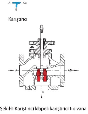
The ARI-STEVI 450 series three-way control valves have DN15-32 diameter valves, standard stirrer type clapper. They can be used either as a dispenser or as a mixer depending on the application. It is only necessary to correctly mount the valve according to the flow directions.


When the mixer clapper design is used as a valve mixer, if the A-AB path is open and the B-AB path is closed, the electric actuator or the pneumatic actuator must move the valve shaft downwards. If the B-AB path is open and the A-AB path is closed, the actuator must move the valve shaft upwards. When the air is cut off in the pneumatic actuator or when the electric actuators with fault safety function are cut off, the actuator A-AB is open and the actuator B-AB is closed. If necessary, the actuator must drive the valve shaft. If the opposite is desired, the actuator should pull the valve shaft in. The agitator function is used to achieve a fluid with a lower temperature by mixing two fluids.

If the valve has a diameter between 15 and 32 diameters and is installed in the appropriate directions when used as a distributor, then the path of AB-A is open and the path of AB-B is closed; the electric actuator or the pneumatic actuator must move the valve shaft downwards. If AB-B path is open, AB-A path is closed, the actuator should move the valve shaft upwards. When the air is cut off in the pneumatic actuator or when the electric actuators with fault safety functions are cut off, the AB-A path is open, the AB-B path is closed and the actuator is driven out of the valve shaft if desired. If the opposite is desired, the actuator should pull the valve shaft in. The agitator function is used to mix two fluids to obtain a fluid with a lower temperature.


It should be noted that products can be used as mixers or dispensers at the order step between DN40-150 diameters. In accordance with the application of the flap designs between these diameters; mixer flap for mixer application, dispenser flap design for dispenser application. For dispenser application, the electric actuator or pneumatic actuator must move the valve shaft upward if the AB-A path is open and the AB-B path is closed with the dispense valve design. If the AB-B path is open, the AB-A path is closed, the actuator should move the valve shaft downwards.When air is cut off in the pneumatic actuator or power is cut off in the electric actuator with the fault safety function, the AB-A path must be open, the AB-B path closed, and the actuator valve shaft should be pulled in if desired. If the opposite is desired, the actuator should drive the valve shaft out. The dispensing application is used to heat or cool another fluid by means of a heat exchanger with the incoming fluid. When the desired temperature is reached, AB-B is open and AB-A is closed.


For proportional control in electric actuator; floating control voltage supply, 4-20mA analog signal input, or 0-10V digital signal input, in some cases it may be necessary to reverse connect the poles or reverse from the process controller. For proportional control in pneumatic actuator; the electro-pneumatic positioner may require reversing the polarity of the 4-20mA analog signal input poles or reversing the process controller.


Source: ARI-Armaturen Turkey Ayvaz Product Manager Ersun Gürkan